
Architectural Informatics 2 |
AutoCAD 2D·3 • Documentation |
Digital Representation |
 Exercise: furnish and finalise last week's plan!


•> -Block
(•>specify a name for the block) Window-120
(•>define an insertion point for the block)
(•>select the elements of the block, then) [Enter]
» If you use the dialog box (Block), make sure to use the ¤ Convert to block option!

Select the name of the block from the list, make sure to set the Specify On-Screen options in the Insertion Point, and Rotation sections, then click on [OK] button, and specify the location and rotation of the block!
» Component objects of a block drawn on layer 0 will be placed on the layer the block is inserted on. In any other case the component will stay on its original layer.
» Component objects of a block having color and/or linetype ByLayer will inherit the color and/or linetype of the layer on which it resides.
» Component objects of a block having color and/or linetype ByBlock will inherit the color and/or linetype of the block (which in turn can inherit the properties of the layer it is inserted on).
» Component objects of a block having a specific color and/or linetype assigned to them will obviuosly keep their original properties.
• Use the REFedit command (Tools • Xref and Block Editing > Edit Reference In-Place), and select the block you want to modify. Click on the [OK] button of the dialog box that comes up next. Select every component and set their color to ByBlock, then save the changes using the last button of the Refedit toolbar (RefClose).
» You can add or remove components to or from the block using the [+] or [–] buttons of the toolbar.
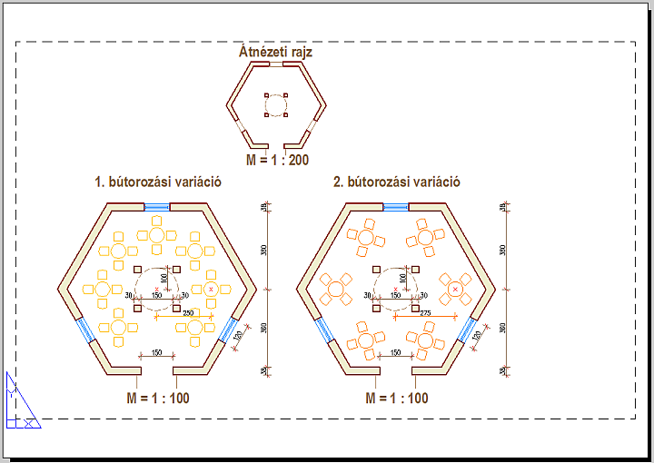

The Model tab accesses a limitless drawing area called model space. In model space, you draw, view, and edit your model. Layout tabs access an area called paper space. In paper space, you place your title block, create layout viewports to display views, dimension your drawing, and add notes. You can access model space from a layout (e.g. by double-clicking within a viewport) to edit objects, to freeze and thaw layers, and to adjust the view. You can return to paper space by double-clicking outside the viewport.

You can use the MView (View • Viewports > 1 Viewport) command to create a viewport with the given size.
•> MView 10,10 @110,100.
» In paper space, one unit represents the paper distance on a plotted sheet. The units can be in either millimeters or inches.
» If you want to hide the border of the viewport, place it on a different layer, and switch that layer Off!
» The Object option of MView can be used to convert a closed polyline, ellipse, spline, region, or circle into a viewport.
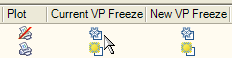

Double-click inside the viewport, then in the Layer Properties Manager use the column labeled Current VP Freeze to freeze the FURN-2 layer in the current layout viewport!

In model space, you can use the Center option of Zoom to set the position and the scale of the plan.
•> Zoom Center 0,0 10XP
» A value followed by XP specifies the scale relative to paper space units. 10XP means that a 1 meter long line (m = model space drawing unit) will be 1 millimeter long on the paper (mm = paper space drawing unit).
» In paper space you can enter the same scale in the Custom Scale field in the Properties palette of the viewport.
» You can modify the list of Standard scales available for layout viewports with the ScaleListEdit command.
» If you want to lock the scale of the viewport select it, then in the Properties palette select Display Locked, and click Yes.

You can use DText (Draw • Text > Single Line Text) to create one or more lines of text, where each text line is an independent object that you can relocate, reformat, or otherwise modify.
The justification of the text should be MC (Middle Center), which centers the text both horizontally and vertically at the middle of the text. The insertion point of the text should be the midpoint of the bottom side of the viewport.
» Text that would otherwise be difficult to read (if it is very small, very large, or is rotated) is displayed at a legible size and is oriented horizontally so that you can easily read and edit it.
» You can later modify the style, size and justification of the text using the Properties palette.
» You can create, erase, and modify the available text styles (e.g. name, font, default size…) with the STyle command (Format • Text Style).
Strommer L. • BME Department of Architectural Representation